CD74HC4067 16-Channel Multiplexer Breakout Board
- Stock: 13 InStock
- SKU: 1613 | DAB050
-
Rs.
64.00 (inc GST)
Rs.54.24 + GSTQty :
GST Invoice on all Purchase. So you will be eligible to take input tax credit. |
IF component not in Stock or require more quantity or want to buy in bulk e-mail us your requirements on: dnatechindia "at" gmail.com. |
| Shipping : Due to Covid-19 situation delivery will be affected. Delivery period due to covid-19 issue will be from 4 - 12 days depending upon your location. |
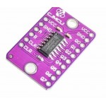
CD74HC4067 16-Channel Analog Digital Multiplexer Breakout Board Module
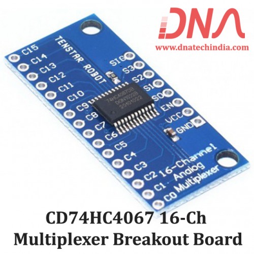
This is a breakout board that mounts a 74HC4067 which is a 16-channel Analog multiplexer/demultiplexer that can route both analog and digital signals in both directions.
1 of 16 input channels can be routed to 1 output or 1 input can be routed to 1 of 16 output channels. It can handle analog signals such as from analog sensors or a bank of potentiometers or it can handle digital signals such as from switches, digital sensors or even serial communications.The 74HC4067 can operate over the range of 2 to 6V, so it is compatible with both 3.3 and 5V logic.
Four address lines (S0-S3) select one of the 16 channels and connects it to the input/output pin (SIG). It uses binary addressing, so address 0000 is Channel 0, address 1111 is Channel 15. When a channel is ON, it has a resistance of about 70 ohms which allows signals to flow both ways. With a 5V power supply, we measured about 60 ohms. Maximum current is 25mA through any of the channels.
There is an enable pin (EN) that is active LOW and defaults to that value. When LOW, the device enables the channel selected by the address lines. If EN is pulled HIGH, all channels are disabled.
On the electronics module there are 2 rows of header solder points. These can be used to connect wires to or header pins depending on the application.
- 1×8 Header Location
- SIG = Signal Input / Output. This will usually connect to an analog input or digital I/O on the microcontroller
- S3 = Binary Address Bit 3. The address bits (3…0) connect to 4 digital output pins on the microcontroller to select channel.
- S2 = Binary Address Bit 2
- S1 = Binary Address Bit 1
- S0 = Binary Address Bit 0
- EN = Enable. Internally pulled LOW to enable by default. Can be pulled HIGH to disable all channels.
- VCC = 2 to 6V. Usually connected to 5V or 3.3V to match the microcontroller power.
- GND = Ground, must be common with the microcontroller.
- 1×16 Header Location
- C15 = Channel 15
- C0 = Channel 0
We have Various sizes of Modules. Check out our complete collection of Modules
If you are in Nashik you can buy this Electronic Component at our local shop at New CBS, Nashik or you can place order online and get it delivered at your doorstep anywhere in India. |
Related Links
NEW Products
Product Page : New Products
Winsen ZE03-SO2 GAS Sensor Module
Winsen ZE03-SO2 GAS Sensor ModuleElectrochemical Detection Module ZE03-SO2ZE03-SO2 Gas sensor can be..
Rs.13,216.00 (inc GST)
Rs.11,200.00 + GST
SKU: 1764 | DAB100
Stock: 2
H9700 2 channel Digital Output Small Optical Encoder Module
H9700 2 channel Digital Output Small Optical Encoder ModuleH9700 Unipolar Hall-Effect Sensor ICThe H..
Rs.1,652.00 (inc GST)
Rs.1,400.00 + GST
SKU: 7439 | DAF661
Stock: 3
DTECH IOT5064A RS485 Serial to Ethernet Converter Bluetooth adapter
DTECH IOT5064A RS485 Serial to Ethernet Converter Bluetooth adapterDTECH IOT5064A RS485 Serial to Et..
Rs.6,486.76 (inc GST)
Rs.5,497.25 + GST
SKU: 7466 | DAG852
Stock: 1
JHD 204 20X4 GREEN LCD DISPLAY CHINESSE
JHD 204 20X4 GREEN LCD DISPLAY CHINESSEJHD 204 20X4 GREEN LCD DISPLAY CHINESSEThis is a 20x4 LCD dis..
Rs.402.09 (inc GST)
Rs.340.75 + GST
SKU: 7663 | DAF077
Stock: 5
Have You Seen
Product Page : Have You Seen
4 Digit DIY Electronic Clock kit Multicolor LED time Week Temperature Date Display with Clear case Cover (blue)
4 Digit DIY Electronic Clock kit Multicolor LED time Week Temperature Date Display with Clear case C..
Rs.796.50 (inc GST)
Rs.675.00 + GST
SKU: 7443 | DAF836
Stock: 5
GPS Module With External Antenna
GPS Module With External AntennaThis is a GPS Module with External Antenna. It is based on Skytra S1..
Rs.1,180.00 (inc GST)
Rs.1,000.00 + GST
SKU: 0397 | DAE263
Stock: 0
AMT1001 Resistive Temperature And Humidity Sensor
AMT1001 Resistive Temperature And Humidity SensorAMT1001 Resistive Humidity and Temperature Sensor M..
Rs.335.12 (inc GST)
Rs.284.00 + GST
SKU: 3291 | DAD402
Stock: 9
ADS1256 24bit High Precision ADC STM32F103C8T6 Module
ADS1256 24bit High Precision ADC STM32F103C8T6 ModuleADS1256 24bit High Precision ADC STM32F103C8T6 ..
Rs.5,198.70 (inc GST)
Rs.4,405.67 + GST
SKU: 7630 | DAF121
Stock: 0
Related Products
PCF8575 IO Expander Module
PCF8575 IO Expander ModulePCF8575 is a 16-bit I2C Input Output Expander IC. This Module is a simple ..
Rs.322.14 (inc GST)
Rs.273.00 + GST
SKU: 1611 | DAB053
Stock: 17
TCA9548A 8-Channel I2C Multiplexer Board
TCA9548A 8-Channel I2C Multiplexer ModuleYou just found the perfect I2C sensor, and you want to wire..
Rs.94.40 (inc GST)
Rs.80.00 + GST
SKU: 1614 | DAB055
Stock: 10
MCU-164 SN74HC164D 8 Bit Shift Register Module
MCU-164 SN74HC164D 8 Bit Shift Register ModuleMCU-164 SN74HC164D 8-Bit Shift Register ModuleSN74HC16..
Rs.174.64 (inc GST)
Rs.148.00 + GST
SKU: 3265 | DAD357
Stock: 5
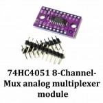
74HC4051 8 Channel Mux Analog Multiplexer Module
74HC4051 8-Channel-Mux Analog Multiplexer Module74HC4051 8-Channel-Mux Analog Multiplexer ModuleThe ..
Rs.142.78 (inc GST)
Rs.121.00 + GST
SKU: 3267 | DAD351
Stock: 9
Adafruit BNO085 9-DOF Orientation IMU Fusion Breakout
Adafruit BNO085 9-DOF Orientation IMU Fusion BreakoutAdafruit BNO085 9-DOF Orientation IMU Fusion Br..
Rs.3,882.20 (inc GST)
Rs.3,290.00 + GST

